Saturday, March 14, 2009

Text Style


A collection of common text properties used by one or more text objects


Predefined text properties such as font, height, width factor, and oblique angle

Create a consistent appearance across drawings by providing predefined text formats
Changing font will update all text using the same text style

Annotative Property
Control the text height to display and plot the same size in the drawing layout, regardless of the viewport scale


3. Match text orientation to layout: text objects display horizontal if the view is isometric
 

Single Line Text


A single word, a letter or a short sentence or phrase

Each line of text or textual object that is created can be edited independently
Able to quickly create and locate small text objects


Place a number or letter inside a circle


Varying heights, justification, and rotation angle is used in a title block

Justification Options


Can copy text from Command Line, Text Window

Multiline Text


An assembly of words, symbols, and other textual information that can be written, formatted, and edited


Click two points to define the text area


Key-in the text

Adjust the boundary by rule to fit the text

The ribbon opens to the Multiline Text tab displaying the Text Editor

1. Style:             Text Style and Height
2. Formatting: Bold, italics, underlined or overlined, font, color
3. Paragraph:   Justification, line spacing, numbering and bullets
4. Insert:           Symbols, columns and fields
5. Options:        Spell check, Replace text, Undo, Redo, Text box Rulers, change case
6. Close

To edit existing multiline text, double-click the text

Copy Text
Copy text from another location or program and paste it into the Text Editor
It may retain the text format associated with its source
Paste the text first into Notepad then copy it again and paste it into the Multiline Text Editor
It retains the text style you designate in AutoCAD

Thursday, March 12, 2009

Viewport 浮动视口

Each viewport acts as a display portal from the paper layout to the geometry in model space


Creating multiple viewports in a single layout, can display different aspects of the model geometry at different scales on the same page
Create viewports on a unique layer and set the properties to No Plot

Viewport Scale Factor
Specific scale compared to the paper units to display the geometry within it

Moving, Copying, and Resizing Viewports
Move:   change a viewport's position on the paper
Copy:    duplicate the viewport and its display settings to another location on the layout
Resize:  use the grips at its corners

Erasing Viewports
Since it only displays a view of the geometry from model space, deleting the viewport does not delete the geometry

Freeze Current Viewport
Display the same area of model space in different ways in each viewport


Double-click inside the viewport to make it active (current)
1. Freeze the layer in current viewport
The layer will frozen in current viewport only and remain thaw in other viewport

Viewport Override
Override layer properties in each viewport to have them appear differently in a viewport than they do in model space


Four properties can control are VP Color, VP Linetype, VP Lineweight, and VP Plot Style

Layout 布局


Prepare drawing for plotting


A layout is an environment used to output drawing data


Paper size
Printable area:  Dashed Lines
Viewport:           Solid Rectangle


One advantage of using layouts is being able to plot using multiple scale factors on the same drawing sheet

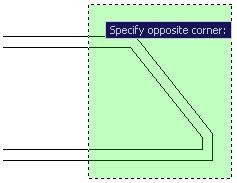
Stretch 拉伸


Change part of an object's shape

Parallel
 
Intersect
 

Defining the stretch operation with a crossing window or crossing polygon is critical

Chamfer 倒角


Create an angled intersection on objects


Create a line between two nonparallel lines as a beveled edge

Distance Option

Specify Distance 1 and Distance 2
Distance 1 will apply on the 1st select object

Angle Option

Specify Distance and Angle
Distance will be apply on the 1st select object

Method Option
Switch between the Distance or Angle methods


Fillet 圆角


Create radius geometry connecting two objects

Zero Radius
 
Act as a Trim command

Specify Radius
 
Rounded off corner

No Trim Option


Polyline Option

Fillets all vertices of a polyline's object like Rectangle, Polygon

Multiple Option
Create multiple fillets without restarting the command

Parallel Lines

Current fillet radius is ignored and an arc is created tangent to both parallel objects

Shift + Select
Override the current radius value and create a radius of 0 Shape corner

Break 打断


Separate objects into two

Specify 1st and 2nd point
Breaks the object leaving a gap between the two remaining pieces

Break at Point 打断于点


Breaks the object at one point, leaving the ends coincident (touching)

Circles break in a counter-clockwise direction
Use Break command only when there are no cutting edges

Join 合并


Combine individual segments of like objects into a single object

Line + Line

All will join
Both lines must be collinear

Line + Polyline
With gap:       Not join
Without gap:  Join
                    Polyline must be a source object
Overlap:        Not join

 
Polyline and line can be join in coplanar

Arc + Line

Not join

Arc + Polyline

Join

Arc + Arc

2 arcs must share the same circular path
Same center point, same radius


Join Direction: CCW